RC Switch With Relay
The Pololu RC Switch with Relay is a radio-controlled switch that can control various devices using standard radio control pulses. The switch can be used with both hobby-grade RC systems and industrial-grade applications. For example, it can be used to turn on a motor or irrigation valve.
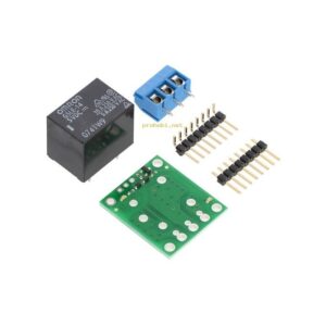
The Pololu RC switch relay has five pins that are spaced about 0.1″ apart. It comes with a printable schematic that shows the logic interface, RC signal input, and relay output. The schematic shows how to measure the pulse width of the RC signal and then connect it to the Pololu’s relay.
When using this switch, it is important to make sure that the relay is connected to the load. The load is the device that you wish to control. It is important to connect the negative power supply terminal to the other side of the load. It does not necessarily need to be connected to the GND pin on the logic side.
The Pololu RC Switch With Relay
The power supply for the Pololu RC Switch with Relay should be at least 2.5 V. This power supply can be provided by the RC receiver or a microcontroller. Its 0.1 header pins can be connected to a ground or reference voltage. The OUT1-OUT4 outputs are also directly connected to standard RC servos.
In the safe-start mode, the LED will do a double blink. It is important to make sure that the pulse is at least three milliseconds wide in order for it to be energized. If the signal is too short, the switch will deactivate. Also, be aware of the hysteresis, which is 64 milliseconds.
If the power supply is too low, the Pololu RC Switch with Relay may activate unexpectedly. This is a common problem with RC devices and it is important to check the voltage levels of your system before using it. This switch’s threshold may be set using RC pulses. You may need to power cycle your transmitter and receiver for this purpose.
The Pololu RC Switch with Relay is designed for hobby use. The four channel multiplexer of hobby radio control pulses makes switching between two independent signal sources easy. The auxiliary channel selects output from either the master or slave source. The activation threshold and direction can be adjusted for each channel. The device is constructed from surface-mount components. Its through-hole counterpart requires soldering.
This board uses a 2.5-5.5 V power source. It can be powered by a four or five-cell NiMH or NiCD battery pack. You can also power the device through an RC receiver. This board also supports a learning mode jumper. In order to configure the Pololu RC Switch with Relay, you must make sure that both the VIN and VCC pins are connected.